Understanding Optical Fiber Dispersion and Compensation Strategies: A LiteLinx Perspective
Fiber‑optic networks have revolutionized communications by enabling high‑bandwidth links over great distances. Yet a fundamental limitation remains: dispersion, the spreading of an optical pulse as it travels down the fiber. When dispersion is not carefully managed, the pulse broadens and overlaps with adjacent bits, increasing bit‑error rates and limiting transmission distance. This article summarises the three main dispersion mechanisms (modal, chromatic and polarisation‑mode dispersion) and explores common compensation techniques.
 What Is Optical Fiber Dispersion?
Dispersion refers to the process in which an optical pulse spreads out in time as it propagates along a fiber. The energy of a narrow pulse becomes smeared over a longer period, making it harder for the receiver to distinguish between logical 1 and 0. In general, dispersion arises from three independent phenomena:
· Modal dispersion – different paths (modes) in a multimode fiber have different lengths, so rays arriving at the receiver have different transit times.
· Chromatic dispersion – different wavelengths of light travel at slightly different speeds in a single‑mode fiber; material dispersion relates to the refractive index of the core material and waveguide dispersion to the fiber geometry.
· Polarization‑mode dispersion (PMD) – due to slight asymmetries in the fiber, different polarization states propagate at slightly different speeds.
Dispersion is not always detrimental. In wavelength‑division multiplexing (WDM) systems it can help reduce nonlinear effects by lowering optical power density. Nonetheless, modern gigabit and terabit networks must control dispersion to maintain tight system budgets.
Modal Dispersion
How modal dispersion arises
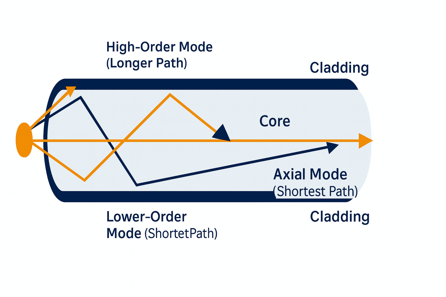
Multimode fibers can support many propagation paths. Light rays entering at different angles travel through different modes; high‑order modes zig‑zag off the cladding while low‑order modes follow near‑axial paths. Because the high‑order path is longer, pulses arriving through that mode are delayed relative to those travelling along the shorter axial path. As the length of the fiber increases, these delays accumulate, and the pulse broadens.
In step‑index multimode fiber, the refractive index is uniform across the core. Such fibers can support up to 17 modes, which leads to significant modal dispersion. By contrast, graded‑index multimode fibers gradually reduce the refractive index from the core centre to the cladding; rays in outer regions travel faster, compensating for their longer paths and reducing modal dispersion.
Mitigating modal dispersion
The most effective way to eliminate modal dispersion is to use single‑mode fiber. With only one propagation path, a single‑mode fiber carries light along the core axis; there is no intermodal delay. Single‑mode fibers operating in the 1310 nm and 1550 nm windows are therefore the backbone of long‑haul networks and FTTH deployments.
Chromatic Dispersion
Chromatic dispersion arises because different wavelengths experience slightly different propagation velocities in a fiber. It is the sum of material dispersion—variation of the refractive index with wavelength—and waveguide dispersion, which depends on the fiber core radius and refractive‑index profile. At some wavelengths these two effects cancel each other; for standard single‑mode fiber this occurs around 1310 nm, resulting in approximately zero dispersion. At 1550 nm the dispersion is positive but small.
Chromatic dispersion tends to spread pulses over long distances, but it also allows designers to tailor fibers for specific applications. For example, ITU‑T G.652.D fibers are engineered for a balance of low attenuation and moderate dispersion in the C‑band; G.655 dispersion‑shifted fibers move the zero‑dispersion wavelength closer to 1550 nm. G.657 bend‑insensitive fibers, like those used in LiteLinx fiber optic cables, are designed for tight bend radii while maintaining low attenuation and controlled dispersion.
Polarization‑Mode Dispersion (PMD)
Polarization‑mode dispersion represents the difference in propagation speeds between orthogonal polarisation states. In an ideal circular fiber the two polarisation axes have identical propagation constants. Manufacturing imperfections, core asymmetry or external stresses (e.g., cabling and installation) introduce birefringence, causing one polarisation to arrive slightly earlier than the other. The differential group delay accumulates randomly along the fiber and scales with the square root of distance.
PMD has little impact on networks operating below 2.5 Gb/s over short distances, but it becomes a critical parameter for high‑speed (>10 Gb/s) or long‑haul links. The total PMD of a system is not only determined by the fiber itself; improper installation, excessive bending or poorly controlled splices can increase PMD. Minimising polarisation effects therefore requires careful handling and documentation of every component and installation step.
Why Dispersion Compensation Is Needed
Dispersion doesn’t weaken the signal directly, but it blurs the waveform. A pulse of 1 ns at the transmitter may broaden to 10 ns at the receiver without compensation, preventing correct decoding and limiting the distance over which data can be transmitted. Dispersion compensation is therefore critical for long‑haul transmission and high‑data‑rate systems like dense wavelength‑division multiplexing (DWDM) networks. In fiber‑to‑the‑home (FTTH) applications, distances are shorter, but network operators still need to minimise dispersion to ensure reliability and maximise upstream capacity.
Dispersion isn’t always bad
A moderate amount of dispersion can actually be beneficial, since having some dispersion when using WDM helps mitigate nonlinear effects. Engineers therefore strive for an optimum dispersion value: high enough to suppress nonlinearities but low enough to avoid intersymbol interference.
Dispersion Compensation Techniques
Dispersion compensating fiber (DCF)
One common compensation method is to insert a length of dispersion compensating fiber (DCF) that exhibits high negative dispersion. When connected in series with standard fiber, the large negative dispersion of the DCF cancels the positive dispersion accumulated by the transmission fiber. Dispersion compensating fibers typically have a larger core/cladding index difference and may be implemented as part of a pre‑compensation (before the transmission fiber), post‑compensation (after), or symmetric compensation scheme.
DCF modules are widely used to upgrade installed G.652 fiber links for operation in the 1550 nm window; they reduce dispersion penalties without replacing existing cables. LiteLinx’s strong portfolio of single‑mode cables—with consistent geometry and low attenuation—pairs well with DCF modules in DWDM networks.
Fiber Bragg grating (FBG)
Fiber Bragg grating devices contain a periodic modulation of the core refractive index along a short fiber segment. The grating reflects different wavelength components with different delays, producing negative group‑delay dispersion. By tailoring the grating profile, FBGs can compensate chromatic dispersion over specific wavelength ranges. They are passive, lightweight and relatively low‑loss; in addition to dispersion compensation, FBGs are used as wavelength stabilisers, sensors and pump‑laser reflectors.
Electronic dispersion compensation (EDC)
Electronic dispersion compensation uses digital signal processing to counter dispersion impairments after optical‑to‑electrical conversion. An electronic equaliser is inserted in the receiver path, effectively implementing a filter whose taps correspond to time‑delayed copies of the signal. The filter coefficients adapt automatically, allowing EDC to compensate for varying dispersion. EDC can be used with both single‑mode and multimode fibers and is common in 10 Gb/s and 25 Gb/s transceiver designs.
Hybrid approaches
Large‑scale DWDM systems often use a combination of DCF, FBG and EDC. Dispersion compensating fibers handle the bulk of chromatic dispersion; FBGs fine‑tune residual dispersion or equalise the dispersion slope; and EDC cleans up any remaining intersymbol interference. The appropriate mix depends on the channel spacing, data rate and system architecture.
LiteLinx Products for Dispersion‑Managed Networks
LiteLinx’s Fiber Optic Cables designed for middle and last‑mile deployments. Key features drawn from the product datasheet include:
· Installation flexibility: The cable is engineered for self‑supporting aerial, direct‑buried and duct installations, making it a versatile choice for drop applications.
· Water‑blocked PBT central tube: A PBT (polybutylene terephthalate) tube contains single‑mode fibers compliant with ITU‑T G.652–G.657 (A1, A2 and D category glass) is either dry or filled with a water‑blocking compound to ensure watertightness. This structure also delivers low friction, flexible and kink‑resistant installation.
· Low attenuation and dispersion: The fibers meet or exceed attenuation coefficients of ≤0.36 dB/km at 1310 nm and ≤0.22 dB/km at 1550 nm, ensuring minimal dispersion over drop‑length distances.
By combining a rugged design with single‑mode fibers, cable minimises modal dispersion and supports high‑bandwidth services. Its robust construction and water‑blocking features also minimise macro‑bending and micro‑bending effects, further reducing dispersion penalties.
Conclusion
Dispersion is an unavoidable physical phenomenon that causes optical pulses to broaden as they propagate along a fiber. Modal dispersion arises in multimode fibers due to different path lengths; chromatic dispersion stems from wavelength‑dependent propagation speed; and polarization‑mode dispersion results from birefringence in the fiber and cabling. While some dispersion is useful for mitigating nonlinear effects, excessive dispersion blurs signals and limits bandwidth. Network designers therefore employ a mix of compensation techniques—dispersion compensating fiber, fiber Bragg gratings and electronic equalisation—to maintain signal integrity.
LiteLinx® supports dispersion‑managed networks through both hardware and software innovations. More broadly, the F360i Smart Fiber platform embeds real‑time visibility and automation into every phase of fiber deployment, ensuring that cables are properly installed and that inventory and documentation are meticulously maintained. Together, these solutions empower network owners to build smarter, more efficient and more resilient fiber networks that can deliver high‑bandwidth services well into the future.